Axial Flow Compressor

An axial compressor is a machine that can continuously pressurize gases. It is a rotating, airfoil-based compressor in which the gas or working fluid principally flows parallel to the axis of rotation. This differs from other rotating compressors such as centrifugal compressors, axis-centrifugal compressors and mixed-flow compressors where the fluid flow will include a “radial component through the compressor. The energy level of the fluid increases as it flows through the compressor due to the action of the rotor blades which exert a torque on the fluid. The stationary blades slow the fluid, converting the circumferential component of flow into pressure. Compressors are typically driven by an electric motor or a steam or a gas turbine.

Axial flow compressors produce a continuous flow of compressed gas, and have the benefits of high efficiency and large mass flow rate, particularly in relation to their size and cross-section. They do, however, require several rows of airfoils to achieve a large pressure rise, making them complex and expensive relative to other designs (e.g. centrifugal compressors).

Axial compressors are integral to the design of large gas turbines such as jet engines, high speed ship engines, and small scale power stations. They are also used in industrial applications such as large volume air separation plants, blast furnace air, fluid catalytic cracking air, and propane dehydrogenation. Due to high performance, high reliability and flexible operation during the flight envelope, they are also used in aerospace engines

Axial flow compressors

Axial

Axial compressors are used for very high flow and low-pressure applications. Our product range covers extensive customer requirements, from highly standardized equipment to cutting-edge compression solutions for Liquefied Natural Gas and Gas-To-Liquids plants. In addition, we can supply the complete range of products for the installation, including gas turbines, steam turbines, compressors, control systems, and air coolers.

How Gas Turbine Power Plants Work


The combustion (gas) turbines being installed in many of today’s natural-gas-fueled power plants are complex machines, but they basically involve three main sections:

  • The compressor, which draws air into the engine, pressurizes it, and feeds it to the combustion chamber at speeds of hundreds of miles per hour.
  • The combustion system, typically made up of a ring of fuel injectors that inject a steady stream of fuel into combustion chambers where it mixes with the air. The mixture is burned at temperatures of more than 2000 degrees F. The combustion produces a high temperature, high pressure gas stream that enters and expands through the turbine section.
  • The turbine is an intricate array of alternate stationary and rotating aerofoil-section blades. As hot combustion gas expands through the turbine, it spins the rotating blades. The rotating blades perform a dual function: they drive the compressor to draw more pressurized air into the combustion section, and they spin a generator to produce electricity.

Land based gas turbines are of two types: (1) heavy frame engines and (2) aeroderivative engines. Heavy frame engines are characterized by lower pressure ratios (typically below 20) and tend to be physically large. Pressure ratio is the ratio of the compressor discharge pressure and the inlet air pressure. Aeroderivative engines are derived from jet engines, as the name implies, and operate at very high compression ratios (typically in excess of 30). Aeroderivative engines tend to be very compact and are useful where smaller power outputs are needed.  As large frame turbines have higher power outputs, they can produce larger amounts of emissions, and must be designed to achieve low emissions of pollutants, such as NOx.

One key to a turbine’s fuel-to-power efficiency is the temperature at which it operates. Higher temperatures generally mean higher efficiencies, which in turn, can lead to more economical operation. Gas flowing through a typical power plant turbine can be as hot as 2300 degrees F, but some of the critical metals in the turbine can withstand temperatures only as hot as 1500 to 1700 degrees F. Therefore, air from the compressor might be used for cooling key turbine components, reducing ultimate thermal efficiency.

One of the major achievements of the Department of Energy’s advanced turbine program was to break through previous limitations on turbine temperatures, using a combination of innovative cooling technologies and advanced materials. The advanced turbines that emerged from the Department’s research program were able to boost turbine inlet temperatures to as high as 2600 degrees F – nearly 300 degrees hotter than in previous turbines, and achieve efficiencies as high as 60 percent.

Another way to boost efficiency is to install a recuperator or heat recovery steam generator (HRSG) to recover energy from the turbine’s exhaust. A recuperator captures waste heat in the turbine exhaust system to preheat the compressor discharge air before it enters the combustion chamber. A HRSG generates steam by capturing heat from the turbine exhaust. These boilers are also known as heat recovery steam generators. High-pressure steam from these boilers can be used to generate additional electric power with steam turbines, a configuration called a combined cycle.

A simple cycle gas turbine can achieve energy conversion efficiencies ranging between 20 and 35 percent. With the higher temperatures achieved in the Department of Energy’s turbine program, future hydrogen and syngas fired gas turbine combined cycle plants are likely to achieve efficiencies of 60 percent or more. When waste heat is captured from these systems for heating or industrial purposes, the overall energy cycle efficiency could approach 80 percent.

Turbocharger

An engine is designed to burn a fuel-air mixture to produce mechanical energy. The mechanical energy then moves pistons up and down to create the rotary motion that turns the wheels of a vehicle. The more mechanical energy, the more power the engine can produce.

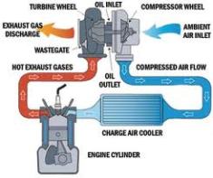
A significant difference between a turbocharged diesel engine and a traditional naturally aspirated gasoline engine is that the air entering a diesel engine is compressed before the fuel is injected. This is where the turbocharger is critical to the power output and efficiency of the diesel engine. It is the job of the turbocharger to compress more air flowing into the engine’s cylinder. When air is compressed the oxygen molecules are packed closer together. This increase in air means that more fuel can be added for the same size naturally aspirated engine. This generates increased mechanical power and overall efficiency improvement of the combustion process. Therefore, the engine size can be reduced for a turbocharged engine leading to better packaging, weight saving benefits and overall improved fuel economy.

Although turbocharging is a relatively simple concept, the turbocharger is critical to the operation of the diesel engine and therefore requires a highly engineered component. Our extensive experience in turbocharging technology and knowledge of engines combines for world-class design and manufacture of Holset Turbochargers, renowned for their durability, high standard of safety, and reliable performance that engines demand.

How does a turbocharger work?
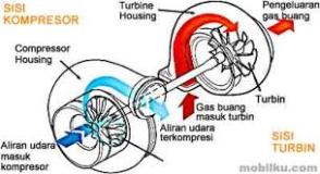
A turbocharger is made up of two main sections: the turbine and the compressor. The turbine consists of the (1) turbine wheel and the (2) turbine housing. It is the job of the turbine housing to guide the (3) exhaust gas into the turbine wheel. The energy from the exhaust gas turns the turbine wheel, and the gas then exits the turbine housing through an (4) exhaust outlet area.

Turbo Diagram(1)  The turbine wheel
(2)  The turbine housing
(3)  Exhaust gas
(4)  E
xhaust outlet area
(5)  The compressor wheel
(6)  T
he compressor housing
(7)  
Forged steel shaft
(8)  Compressed air


The compressor also consists of two parts: the (5) compressor wheel and the (6) compressor housing. The compressor’s mode of action is opposite that of the turbine. The compressor wheel is attached to the turbine by a (7) forged steel shaft, and as the turbine turns the compressor wheel, the high-velocity spinning draws in air and compresses it. The compressor housing then converts the high-velocity, low-pressure air stream into a high-pressure, low-velocity air stream through a process called diffusion. The (8) compressed air is pushed into the engine, allowing the engine to burn more fuel to produce more power.

ImageImage

Foundation

Launching the website this summer with a new wave and some words by me

image

When imaginations are transformed into actions then a new transformation takes place & these transformations become part of our lives which becomes our past after as time goes, but the best moments out of the past is called nostalgia or what we call it as beete lamhein. The beete lamhein with true feelings gives a new zeal in life with capability of right thinking tending to judge & move ahead so forever with my nostalgia